DCIM - Data Center Infrastructure Management
What is a Data Center?
A data center can be established in a house or can be set in one or more buildings that provide facility of a centralized computing infrastructure, typically servers, storage, and networking equipment. A well structured data center consists of Room, Rack, Servers, Software, Networking, Power, Cabling, Storage, Infrastructure, Cooling, Environment monitoring and Backup power.
Types of Data Centers:
- Colocation
- Enterprise
- Cloud
- Edge Data Center
- Micro Data Center
Data Center Infrastructure Management (DCIM) is a new genus of software of PrismERP that comes with tools which allows data center operators to achieve the ability to run data center operations more efficiently and improve entire data center infrastructure planning and design. When a ERP system is covering all important aspects of a DCIM center - Power, Capacity, Environment, Energy, it increases the ability of operators to identify, locate, visualize, and manage all physical data center assets, and its automatically reduces the cost, labor effort and save the time.
DCIM software is like a bridge of information across organizational territories such as Data Center Operations, Facility infrastructure components (power distribution units [PDUs] and computer room air conditioners [CRACs]), Manpower and IT-related equipment (servers, storage and network switches), and the software will actually minimize utilization of the on-premise data center.
The software will give a complete visual tour of what is happening in the Data center and one can control all the activities by using the manual. The visual information on the equipment in the data center reduces troubleshooting time. And also No need to send someone physically on site frequently.
Through the software one can see a virtual view of a Data center Room with its location number and name, where all the Racks are located with serial number including devices in it. Even when a new Room will be allocated or a new Rack will be set one can also create the same pattern through the software in virtual Data Center space to match up with the real Data Center Room. The operators will get each detail of their Data Center Room through the software without any confusion and complexity.
Introduction
Data Center Infrastructure Management (DCIM) module is a comprehensive solution designed to manage and monitor the physical infrastructure of a data center. It provides tools to efficiently organize, track, and maintain critical assets such as racks, servers, routers, switches, and other hardware components. The module integrates with your ERP system to ensure seamless data flow and real-time updates, enabling better decision-making and operational efficiency.
Scope and Objectives
The primary objective of this user manual is to empower users with the knowledge and skills required to effectively manage data center and server, rack using the enhanced DCIM module. The manual covers all aspects of the module, from initial setup and configuration to advanced datacenter monitoring and reporting.
By following the instructions and guidelines presented in this manual, users will be able to:
Understand the concept of DCIM within PrismERP and its significance for data center and server management.
DCIM module is designed to provide comprehensive management and monitoring of data center infrastructure, including power, cooling, space, and network resources.
It covers the entire lifecycle of data center assets, from planning and deployment to operation.
It supports real-time monitoring, reporting, and analytics to optimize data center performance and resource utilization.
Intended Audience
This user manual is intended for a wide range of users who interact with the enhanced DCIM module of PrismERP. The primary audience includes:
- Data Center Administrators: Responsible for managing and maintaining data center infrastructure.
- IT Managers: Overseeing data center operations and ensuring optimal performance.
- Technical Support Teams: Providing assistance and troubleshooting for the DCIM module.
- General Users: Accessing and utilizing the module for day-to-day operations.
System Requirements
To fully utilize the DCIM module of PrismERP and follow along with this user manual, ensure that your system meets the following requirements:
- A compatible version of PrismERP is installed.
- Sufficient user access rights to configure and use the DCIM module.
- A reliable internet connection for accessing online resources and generating reports.
- Standard hardware and software requirements as specified by PrismERP.
By considering the system requirements and targeting the intended audience, this user manual aims to provide a user-friendly and accessible resource for leveraging the DCIM module within PrismERP effectively. Let's begin exploring the powerful features that will revolutionize your organization's Data Center control and server management.
Getting Started
This chapter focuses on the initial steps to get started with the DCIM module in PrismERP. It provides guidance on installation, setup, user roles, and navigating the module's interface.
Installation and Setup
In this section, you will find instructions on how to install and set up the DCIM module within your PrismERP system. It covers prerequisites, installation procedures, and any additional configurations required to enable the module.
To access this DCIM module goto - Settings> System > System Modules and ensure the module is checked.
User Roles and Permissions
Understanding user roles and permissions is crucial for ensuring appropriate access and control within the DCIM module. This section explains the different user roles available, their respective permissions, and how to assign them to users effectively.
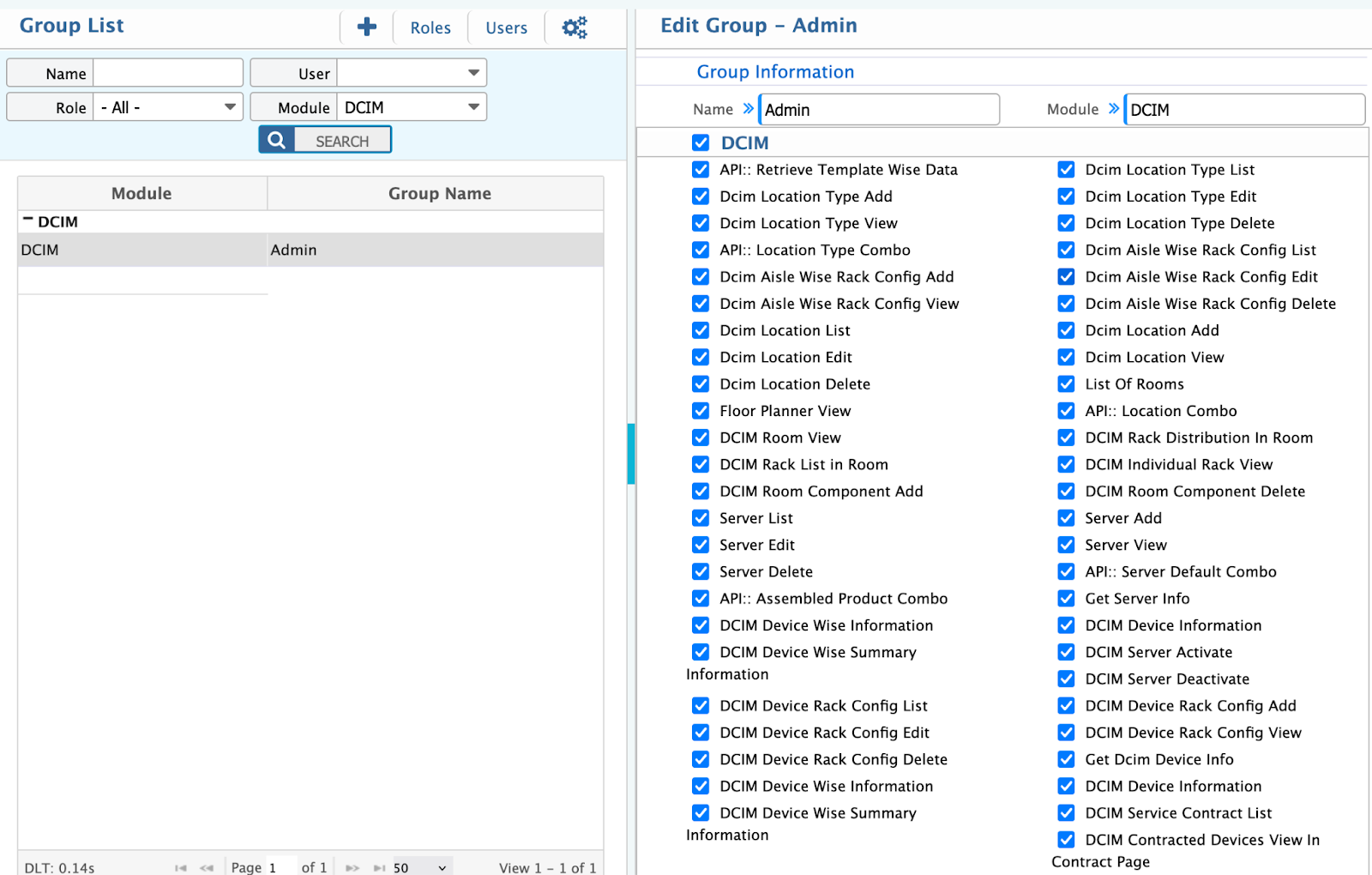
A user role needs to be created with module permission.
Based on user accessibility on the DCIM module different groups with urls permissions need to be created.
By marking an URL means the user is given that permission. But make sure urls permission is given correctly.
Navigating the DCIM Module
Once the module is installed and user roles are assigned, users need to familiarize themselves with the DCIM module's interface. This section provides an overview of the module's main components, navigation menus, and commonly used features.
New Brand and Model & List Brand and Model
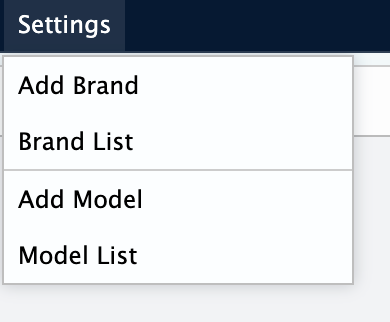
Path: Settings> Add Brand
Path: Settings> List Brand
Path: Settings> Add Model
Path: Settings> List Model
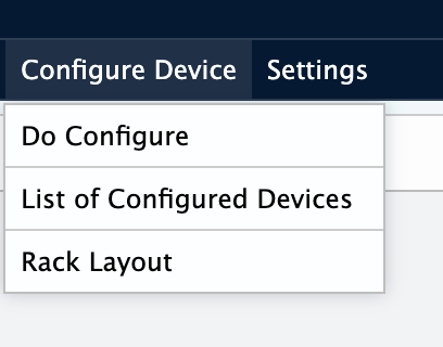
Configure Device
Path: Configure Device> Do Configure
Path: Configure Device> List of Configured Devices
Path: Configure Device> Rack Layout
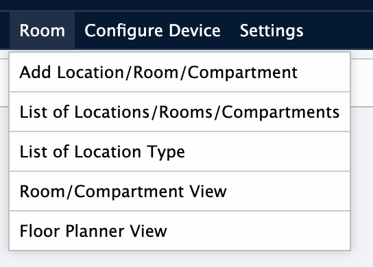
Room
Path: Room> Add Location/Room/Compartment
Path: Room> List of Locations/Rooms/Compartments
Path: Room> List of Location Type
Path: Room> Room/Compartment View
Path: Room> Floor Planner View
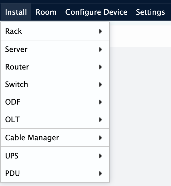
Install
Path: Install> Rack
Path: Install> Server
Path: Install> Router
Path: Install> Switch
Path: Install> ODF
Path: Install> OLT
Path: Install> Cable Manager
Path: Install> UPS
Path: Install> PDU
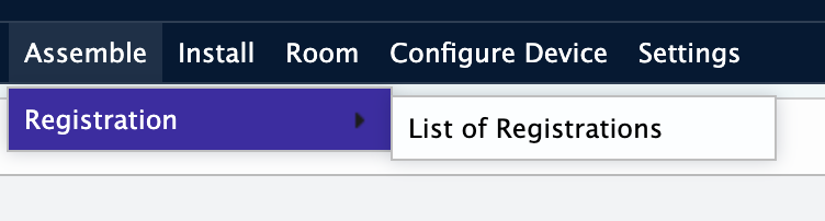
Assemble
Path: Assemble> Registration> List of Registration
In the next chapter, we will drive into the configuration of DCIM settings, enabling you to tailor the module to your organization's specific needs.
Configuring DCIM Settings
This chapter focuses on configuring various DCIM settings to align the module with your organization's specific requirements. It covers brand and model name
Device Settings
In this section, you will learn how to define device brand.
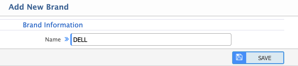
Device Brand
Path: Settings> Add Brand
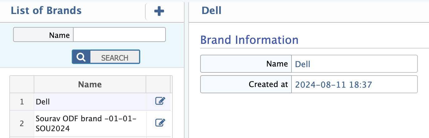
Device Brand List
Device Model
Path: Settings> Add Model
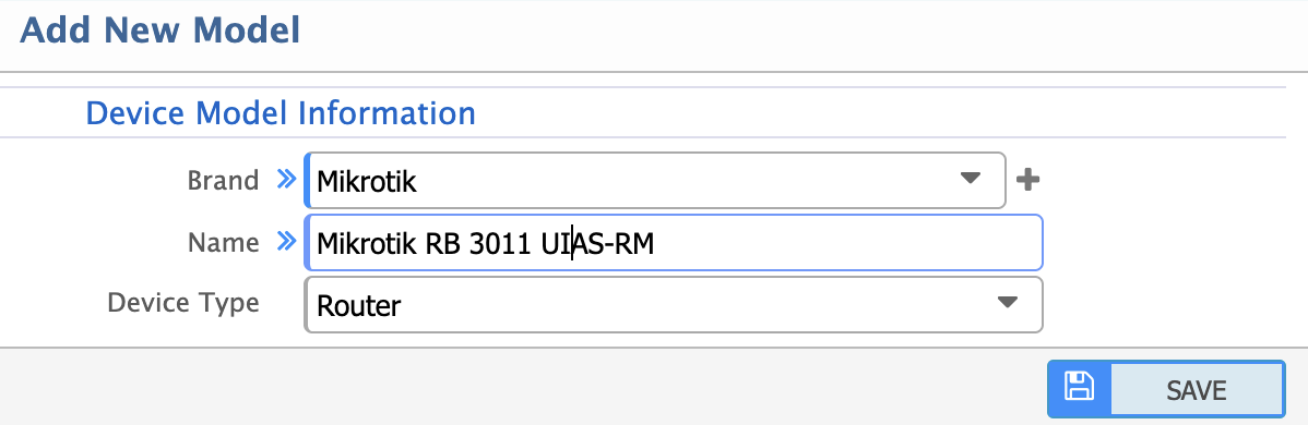
When adding a model, the following details are required:
- Brand: Associated brand for the model which are available in dropdown.
- Name: Name of the model.
- Device Type: Type of device the model belongs to. Options include: Rack, Switch, Router etc.
In the next chapter, we will explore the Data Center Room control and monitoring features of the module, allowing you to track location type, location, room view and floor planner view.
Data Center Room Control and Monitoring
This chapter delves into the features and functionalities that enable you to exercise extensive control over your organization's Data Center and closely monitor Room, Floor, Location within the DC.
Location Type
Path: Room> Add Location Type
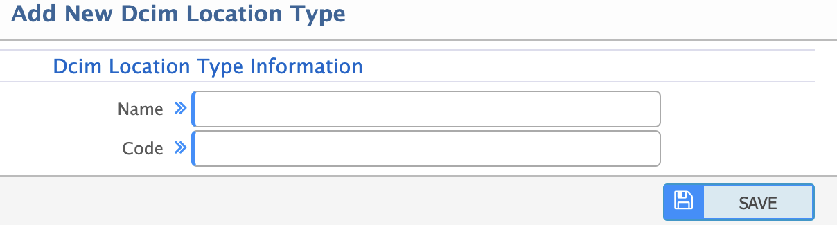
When adding a location type, the following details are required:
- Name: Name of the location type (e.g. Building, Floor, Room).
- Code: Unique identifier for the location type.
Location/Room/Compartment
Path: Room> Add Location/Room/Compartment
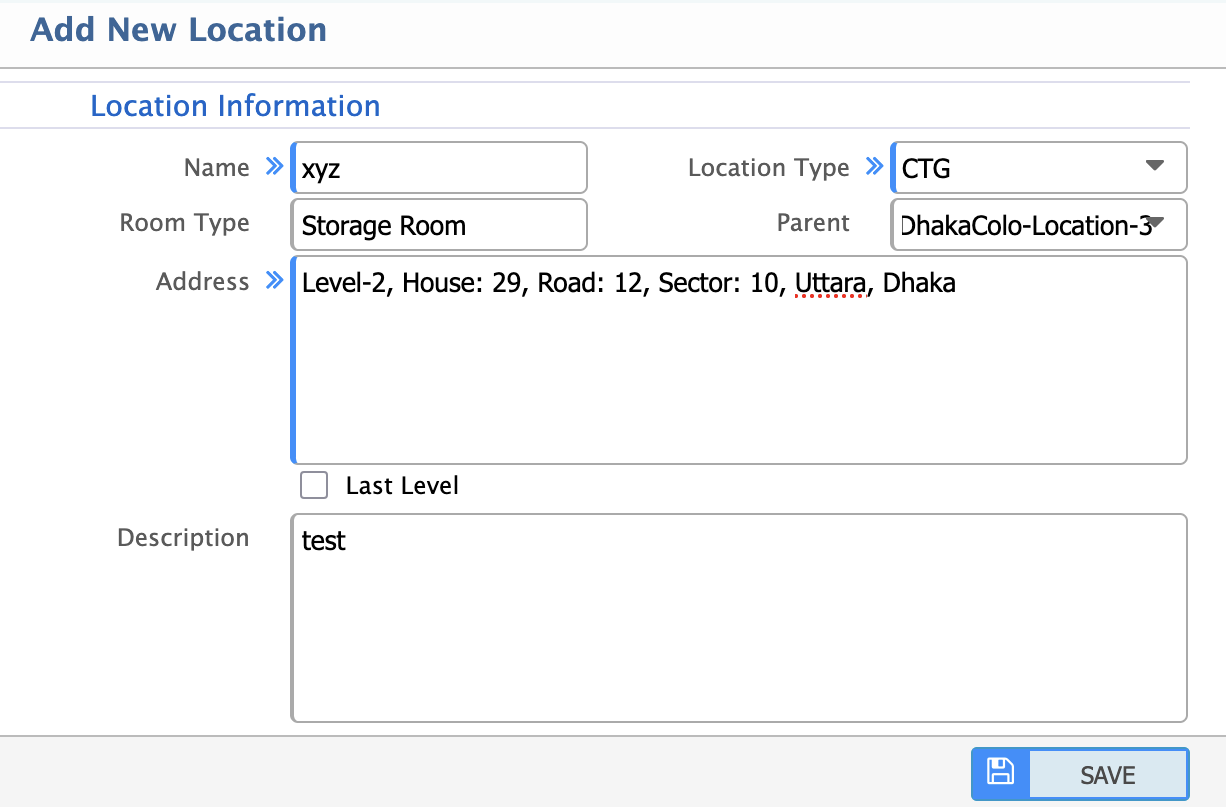
When adding a new location, room or compartment, the following details are required:
- Name: Name of the location, room, or compartment.
- Location Type: Dropdown to select the type of location (e.g. Building, Floor, Room, Compartment).
- Room Type: Type of room (e.g. Server Room, Storage Room).
- Parent Location: The parent location to which this room or compartment belongs (for hierarchical organization).
- Address: Physical address of the location.
- Last Level: Checkbox to indicate if this is the last level in the hierarchy (e.g. a specific compartment within a room).
- Description: Additional details or notes about the location.
Path: Room> List Location/Room/Compartment
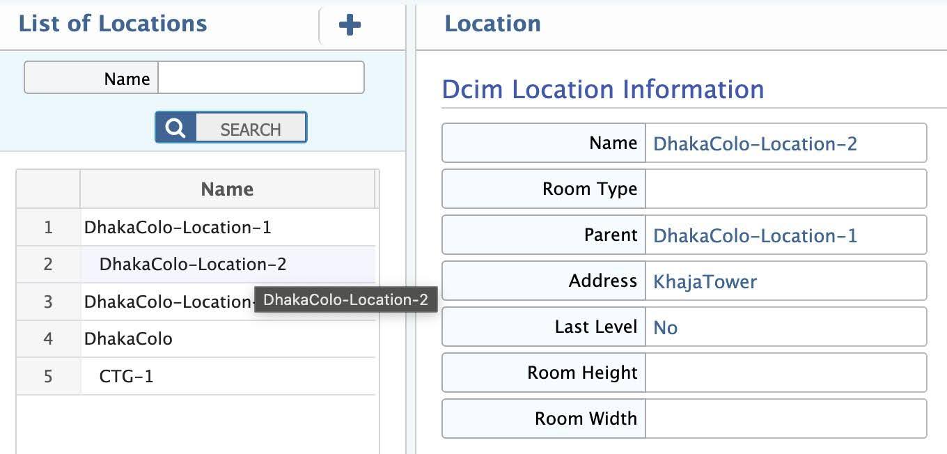
In this section, view a comprehensive list of all locations, rooms, and compartments in the data center. Filter and search for specific locations based on name, type, or parent location.
Room/Compartment View
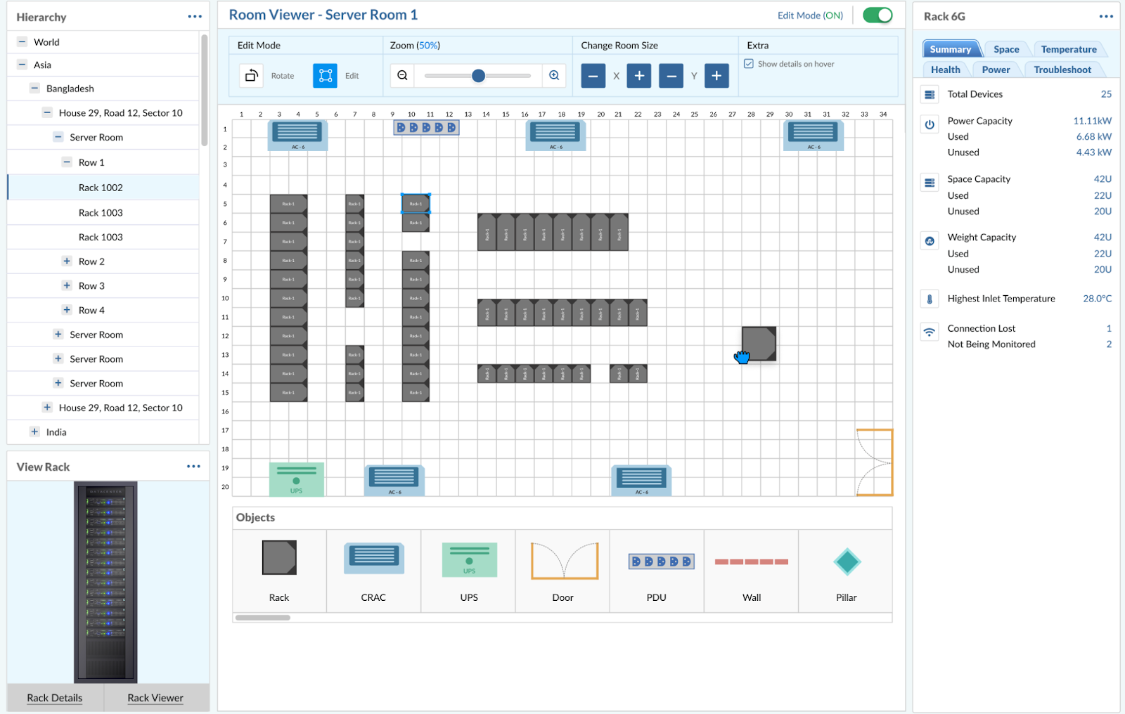
Detailed overview of a specific room or compartment, including:
- Hierarchy: The hierarchy starts from the World level, narrowing down to specific locations in Asia (Bangladesh and India). Server room is divided into rows (Row 1 to Row 4) and specific racks (Back 1002, Back 1003).
- Room Viewer - Server Room 1: The interface allows for editing, zooming, and changing the room size. The current zoom level is set to 50%.
- Summary: Provides an overview of the server room's health, power usage, and temperature.
- Total Devices: 25 devices are present.
- Power Capacity: 11.111 kW, with 6.68 kW used and 4.43 kW unused.
- Space Capacity: 420 units, with 220 used and 200 unused.
- Weight Capacity: 430 units, with 220 used and 200 unused.
- Temperature: The highest inlet temperature is 28.0°C.
- Connection Issues: 1 connection lost and 2 devices not being monitored.
Floor Planner View
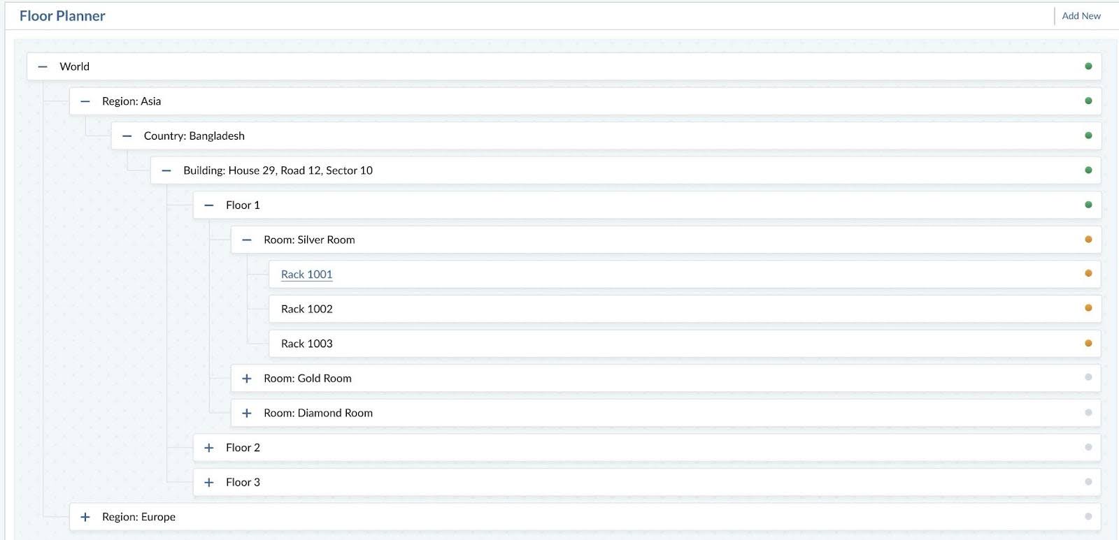
Visual representation of the data center's floor plan, showing as per location add:
- Hierarchical organization of locations, rooms, and compartments.
- Parent-child relationships between locations.
- Layout of racks and devices within each room or compartment.
In the next chapter, we will install the data center devices like rack, server, switch, PDU etc. of the DCIM module.
In the next chapter, we will explore the reporting and analysis capabilities of the DCIM module, empowering you to gain valuable insights into your organization's financial performance and DCIM variances.
Install Devices
This chapter focuses on the installation of devices of the DCIM module in PrismERP. It covers various kinds of device installation into your data center.
Rack
Racks are the foundational units in a data center, housing servers, switches, and other equipment. This section covers the processes and views related to rack management. In this section, you will get an overview of the rack installation of the DCIM module. You will learn about standard details of components that consist of a rack.
Add Rack
Path: Install> Rack> Install Rack
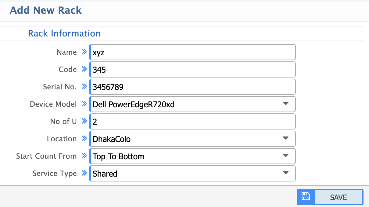
- Name: Unique name for the rack.
- Code: Unique identifier or code for the rack.
- Serial No: Serial number of the rack.
- Device Model: Model number or type of the rack.
- No of Unit: Total number of rack units (U) available in the rack.
- Location: Physical location of the rack in the data center (e.g. row, room number).
- Start Count From: Specify the starting point for counting rack units (e.g. Top to Bottom or Bottom to Top).
- Service Type: Select the type of service the rack will be used for
- Shared: Rack will be used by multiple customers or services.
- Dedicated: Rack will be used exclusively for a single customer or service.
List of Installed Rack
Path: Install> Rack> Installed Rack List
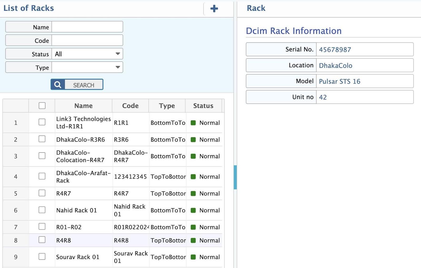
In this section, view a comprehensive list of all racks and their status,type in the data center. Filter and search for a specific rack based on status, type or code.
Rack View
Path: Install> Rack> Rack View
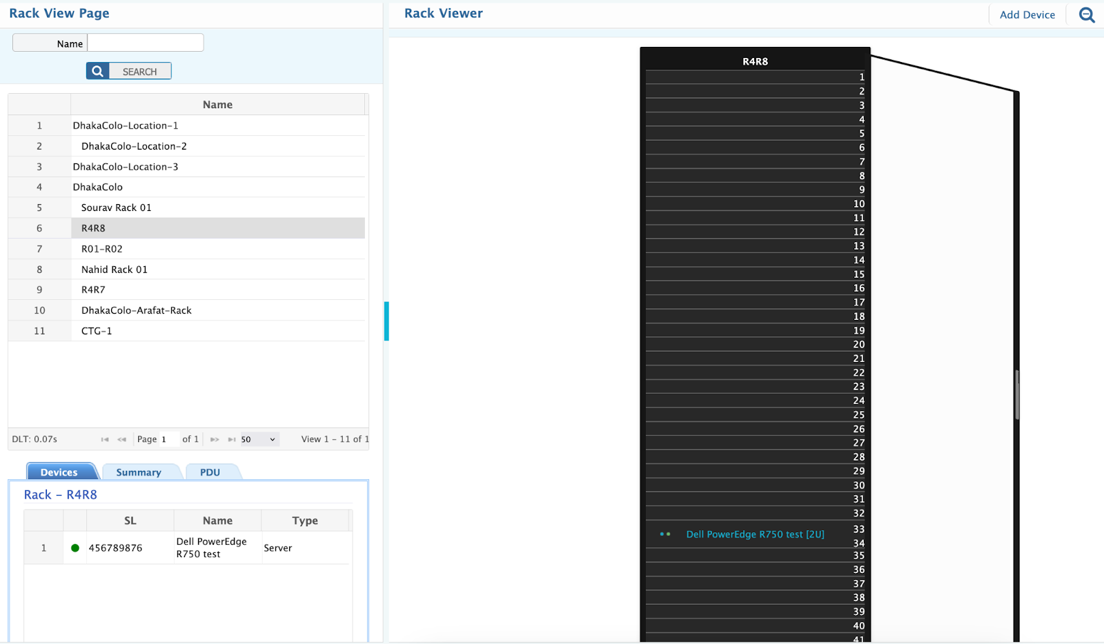
The rack view in a DCIM system is a visual and logical representation of a rack's layout and status. It serves several purposes:
- Visualization: Provides a clear view of the rack's physical layout, including the placement of devices, power distribution.
- Monitoring: Tracks key metrics such as power usage, temperature, and space utilization.
- Management: Allows administrators to manage devices and optimize device resource allocation.
- Planning: Helps in planning for future expansions or reconfigurations by showing available space and power.
Server
A server in a data center rack is a high-performance computer designed to handle network requests, store data and run applications. It is mounted in a standard 19-inch rack and typically comes in 1U, 2U, or 4U sizes.
Server Add
Path: Install> Server> Install Server
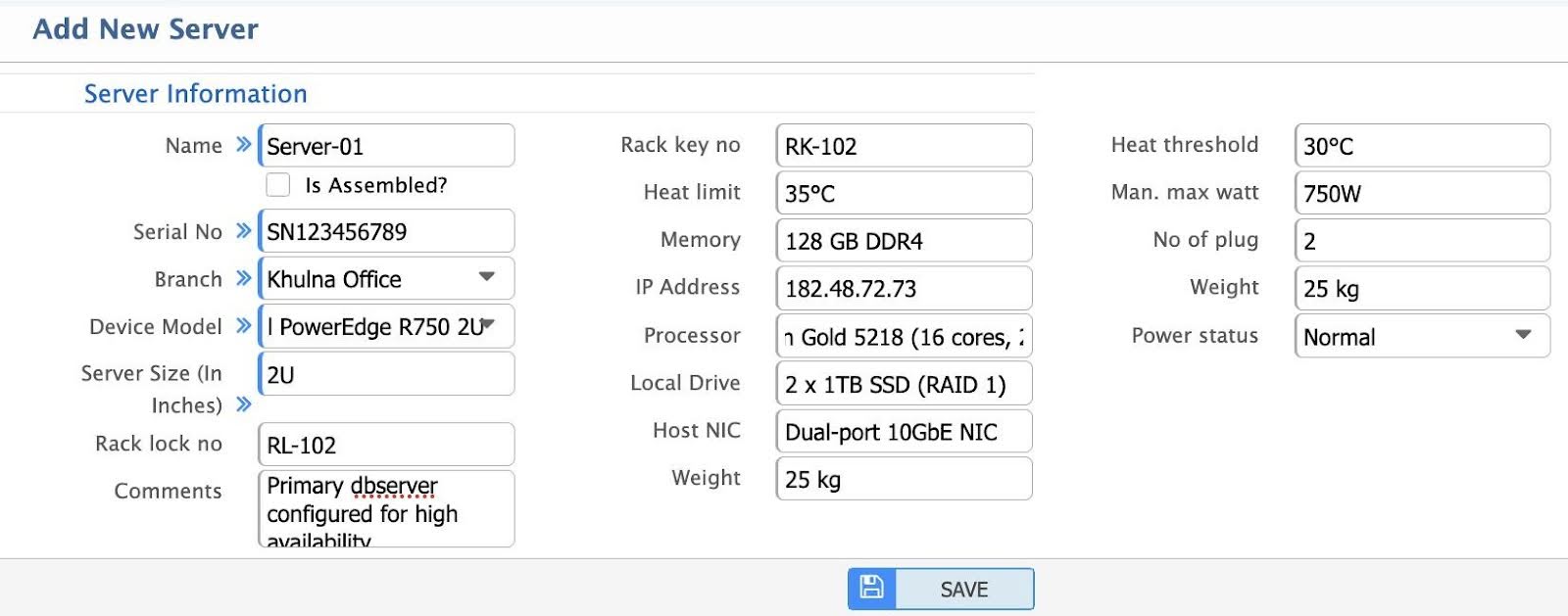
- Name: The name of the server for identification and tracking purposes.
- Is Assembled?: Indicates whether the server is fully assembled and ready for deployment. If marked the check box, Assembled server or product will be available in name dropdown.
- Serial No: Unique serial number of the server for inventory and warranty tracking.
- Branch: The branch or location where the server is installed.
- Device Model: The model of the server, specifying its make and technical specifications.
- Server Size (In Inches): The physical dimensions of the server, typically in height (e.g. 1U, 2U).
- Rack Lock No: Lock number assigned to the rack where server is installed for security purposes.
- Comments: Additional notes or remarks about the server (e.g. special configurations, issues).
- Rack Key No: The key number for accessing the rack where the server is installed.
- Heat Limit: The maximum temperature threshold the server can operate within safely.
- Memory: The amount of RAM installed in the server.
- IP Address: The IP address assigned to the server for network communication.
- Processor: The type and specifications of the server's CPU.
- Local Drive: Details about the local storage drives (e.g. HDD, SSD) installed in the server.
- Host NIC: Information about the Network Interface Card (NIC) used for network connectivity.
- Weight: The physical weight of the server, important for rack load capacity planning.
- Heat Threshold: The temperature limit at which the server may start to overheat.
- Man. Max Watt: The maximum power consumption (in watts) as specified by the manufacturer.
- No of Plug: The number of power plugs required for the server.
- Power Status: The current power status of the server (e.g. Normal, Critical, Warning).
Server List
Path: Install> Server> List of Installed Server
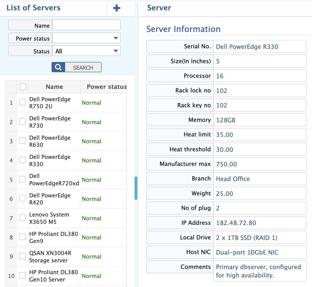
In this section, view a comprehensive list of all servers in the data center. It includes key details such as server names, serial numbers, IP addresses, and statuses. Filter and search for specific Name, power status or active/inactive status.
Router
A router in a data center is a critical networking device that directs data traffic between internal and external networks, ensuring efficient communication between servers, cloud services, and users.
Router Add
Path: Install> Router> Add Router
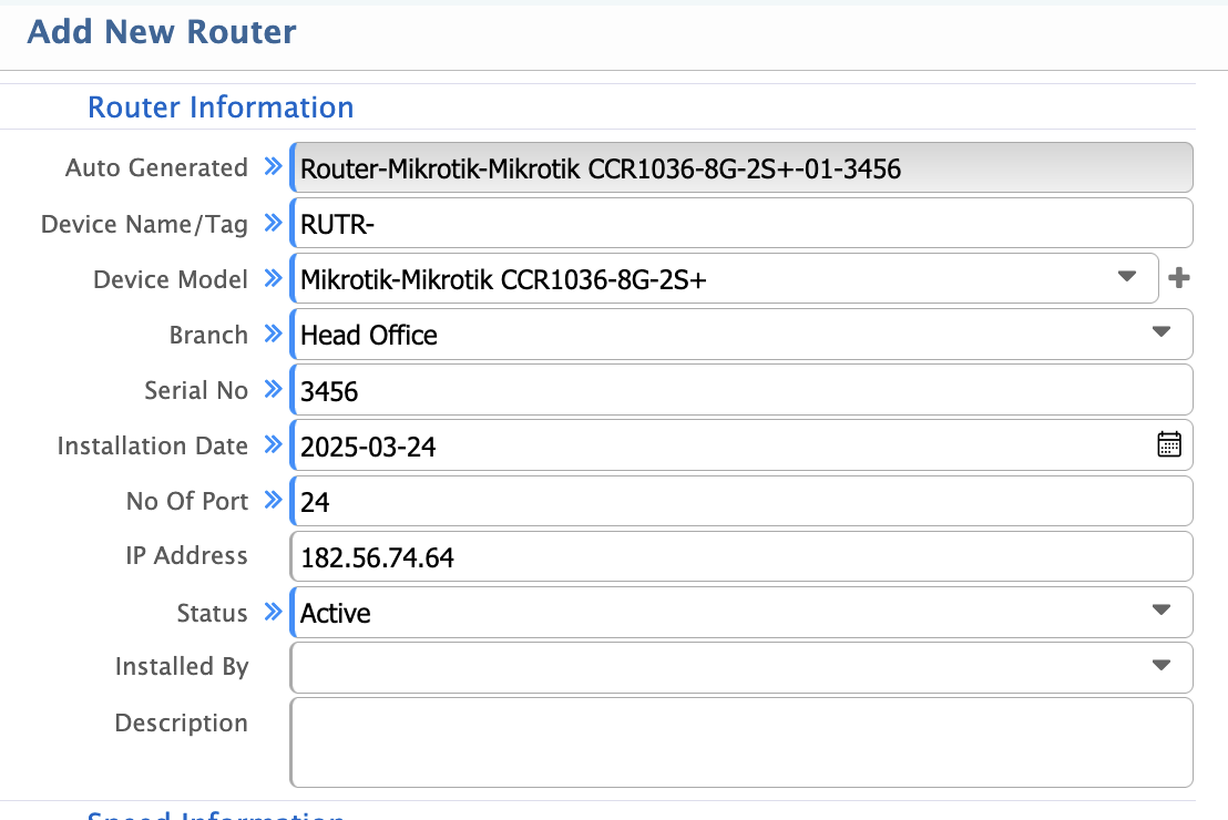
- Auto Generated: Unique identifier automatically generated by the system for the router.
- Device Name/Tag: Custom name or tag assigned to the router for easy identification.
- Device Model: Manufacturer and model of the router (e.g. Cisco ASR 9000).
- Branch: Location or branch where the router is installed.
- Serial No: Unique serial number for inventory and tracking.
- Installation Date: Date when the router was installed.
- No of Port: Total number of ports available on the router.
- IP Address: IP address assigned to the router for management and communication.
- Status: Current operational status (e.g. Active, Inactive, Under Maintenance).
- Installed By: Name or identifier of the person/team who installed the router.
- Description: Additional details or notes about the router (e.g. purpose, configuration).
- Speed Information: Details about the router's speed capabilities.
- Speed: Maximum data transfer speed supported by the router (e.g. 10 Gbps).
- Number of Ports: Total number of physical ports on the router.
Router List
Path: Install> Router> List of Routers
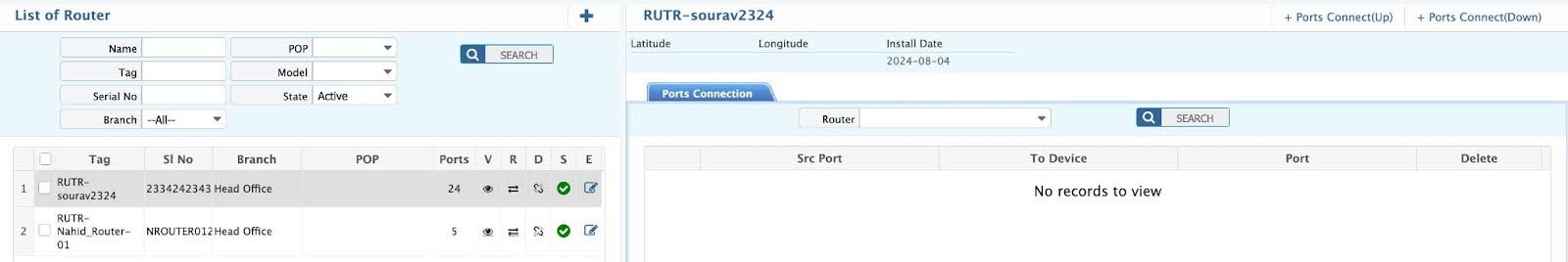
In this section, view a comprehensive list of all routers in the data center. It includes key details such as router names, tag, serial numbers, POPs, models and statuses. Filter and search for specific Name, serial number or active/inactive status.
Switch
A switch in a data center is a high-speed networking device that connects multiple servers and networking equipment within the infrastructure. It enables efficient data transmission by directing traffic based on MAC addresses.
Switch Add
Path: Install> Switch> Add Switch
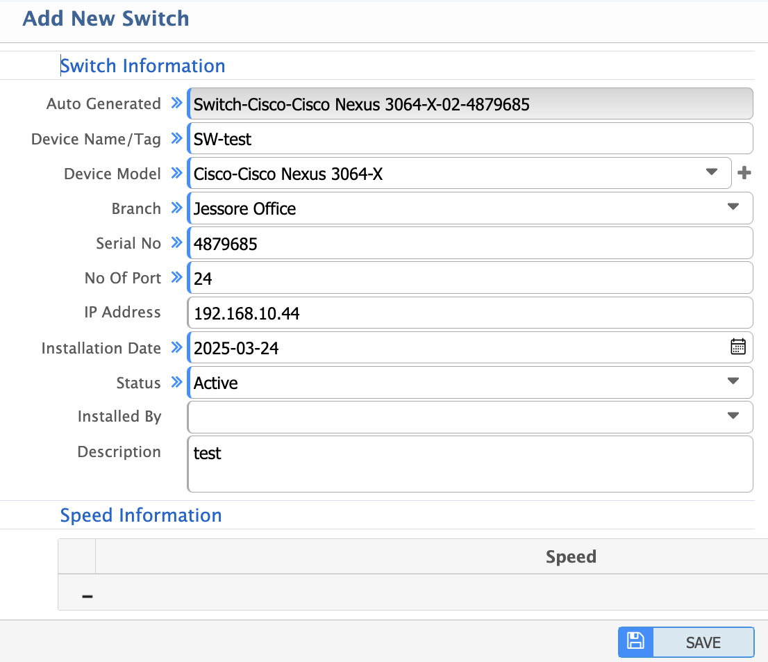
- Auto Generated: Unique identifier automatically generated by the system for the switch.
- Device Name/Tag: Custom name or tag assigned to the switch for easy identification.
- Device Model: Manufacturer and model of the switch (e.g. Cisco Catalyst 9500).
- Branch: Location or branch where the switch is installed.
- Serial No: Unique serial number for inventory and tracking.
- No Of Port: Total number of ports available on the switch.
- IP Address: IP address assigned to the switch for management and communication.
- Installation Date: Date when the switch was installed.
- Status: Current operational status (e.g. Active, Inactive, Under Maintenance).
- Installed By: Name or identifier of the person/team who installed the switch.
- Description: Additional details or notes about the switch (e.g. purpose, configuration).
- Speed Information: Details about the switch's speed capabilities.
- Speed: Maximum data transfer speed supported by the switch (e.g. 10 Gbps).
- Number of Ports: Total number of physical ports on the switch.
Switch List
Path: Install> Switch> List of Switches
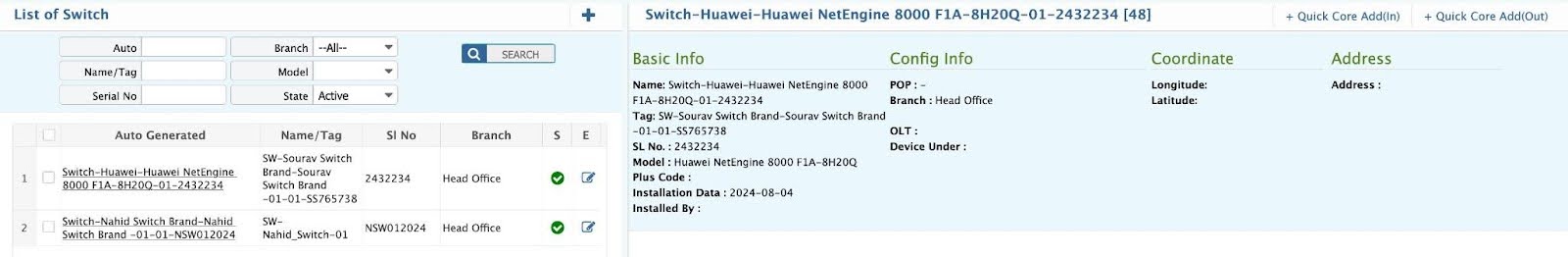
In this section, view a comprehensive list of all switch in the data center. It includes key details such as router names, tag, serial numbers, models and statuses. Filter and search for specific Name, serial number or active/inactive status.
ODF (Optical Distribution Frame)
An Optical Distribution Frame (ODF) is a crucial component in a data center's fiber optic network, organizing and managing fiber connections efficiently. It serves as a termination point for optical cables, ensuring structured cabling and easy maintenance.
ODF Add
Path: Install> ODF> Add ODF
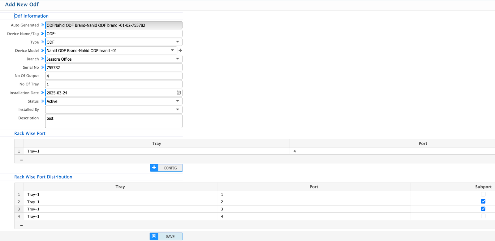
- Auto Generated: Unique identifier automatically generated by the system for the ODF.
- Device Name/Tag: Custom name or tag assigned to the ODF for easy identification.
- Type: Type of ODF (e.g. wall-mounted, rack-mounted).
- Device Model: Manufacturer and model of the ODF.
- Branch: Location or branch where the ODF is installed.
- Serial No: Unique serial number for inventory and tracking.
- No Of Output: Total number of output ports available on the ODF.
- No Of Tray: Total number of trays in the ODF.
- Installation Date: Date when the ODF was installed.
- Status: Current operational status (e.g. Active, Inactive, Under Maintenance).
- Installed By: Name or identifier of the person/team who installed the ODF.
- Description: Additional details or notes about the ODF (e.g. purpose, configuration).
Rack Wise Port
- Tray: Identifier for the tray within the ODF.
- Port: Specific port number within the tray.
Rack Wise Port Distribution
- Tray: Identifier for the tray within the ODF.
- Port: Specific port number within the tray.
- Subport: Sub-port or channel within the main port (if applicable).
ODF List
Path: Install> ODF> List of ODF
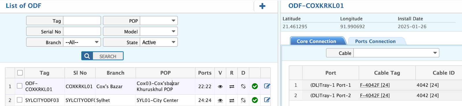
In this section, view a comprehensive list of all ODF in the data center. It includes key details such as router names, tag, serial numbers, POPs, models and statuses. Filter and search for specific Name, serial number or active/inactive status.
OLT (Optical Line Terminal)
An Optical Line Terminal (OLT) is a key component in a data center's fiber-optic network, responsible for managing and transmitting data between core networks and multiple Optical Network Units (ONUs) or Optical Network Terminals (ONTs). It is widely used in Passive Optical Networks (PON) for high-speed internet distribution.
OLT Add
Path: Install> OLT> Add OLT
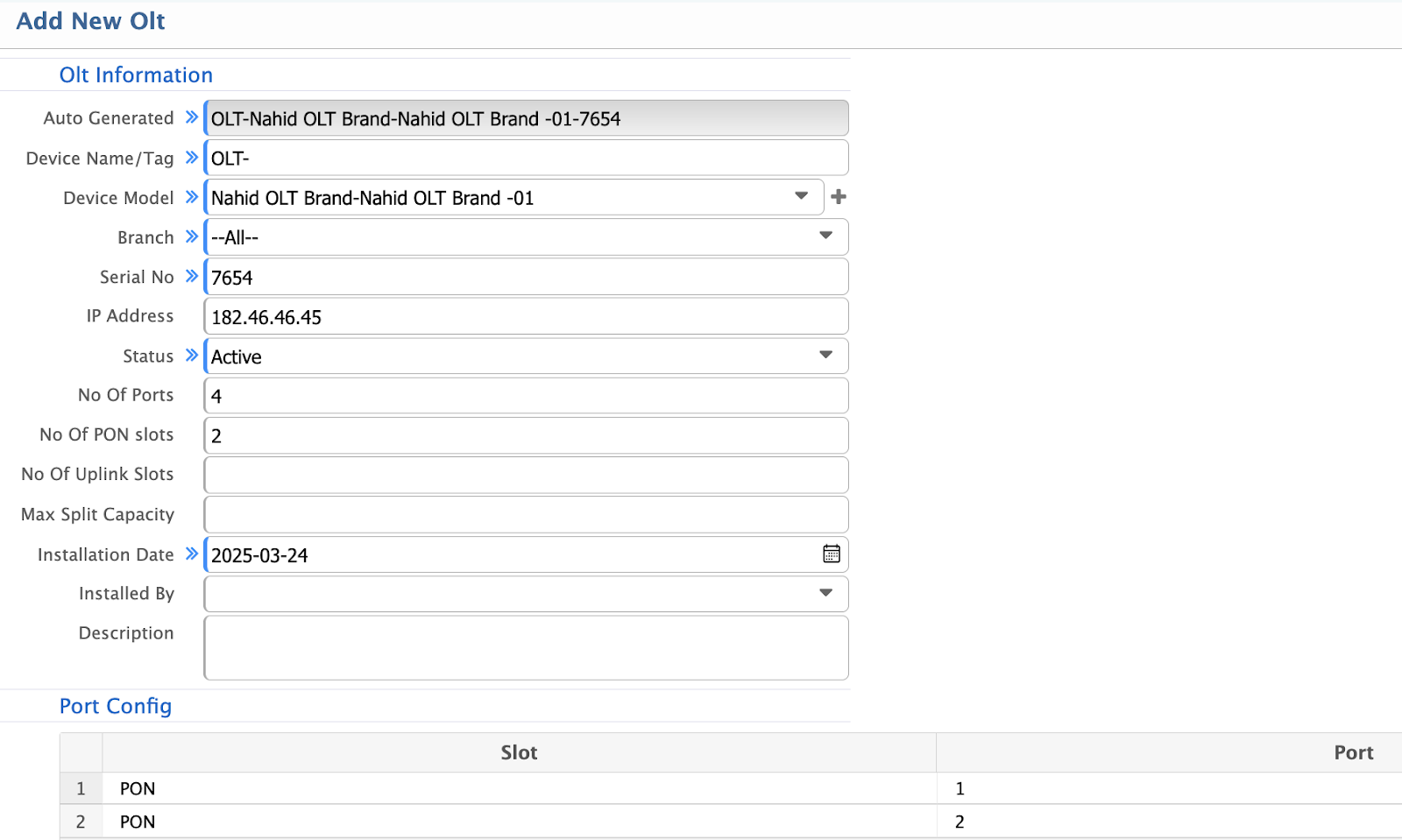
- Auto Generated: Unique identifier automatically generated by the system for the OLT.
- Device Name/Tag: Custom name or tag assigned to the OLT for easy identification.
- Device Model: Manufacturer and model of the OLT (e.g. Huawei MA5608T).
- Branch: Location or branch where the OLT is installed.
- Serial No: Unique serial number for inventory and tracking.
- IP Address: IP address assigned to the OLT for management and communication.
- Status: Current operational status (e.g. Active, Inactive, Under Maintenance).
- No Of Ports: Total number of ports available on the OLT.
- No Of PON Slots: Number of PON (Passive Optical Network) slots in the OLT.
- No Of Uplink Slots: Number of uplink slots for connecting to the core network.
- Max Split Capacity: Maximum number of splits supported by the OLT (e.g. 1:64).
- Installation Date: Date when the OLT was installed.
- Installed By: Name or identifier of the person/team who installed the OLT.
- Description: Additional details or notes about the OLT (e.g. purpose, configuration).
Port Config
- Slot: Identifier for the slot in the OLT.
- Port: Specific port number within the slot.
- Speed: Data transfer speed supported by the port (e.g. 1 Gbps, 10 Gbps).
OLT List
Path: Install> OLT> List of OLT
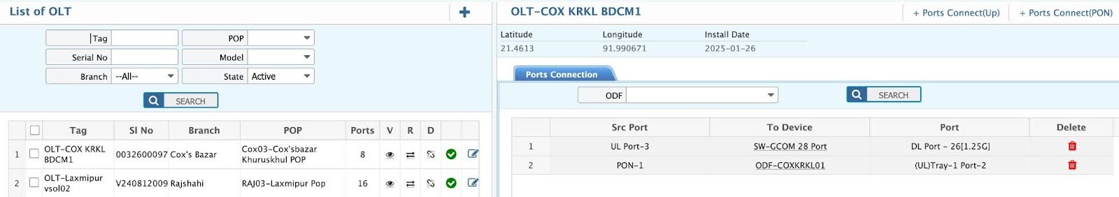
In this section, view a comprehensive list of all OLT in the data center. It includes key details such as names, tags, serial numbers, POPs, Ports and statuses. Filter and search for specific Name, serial number or active/inactive status.
Cable Manager
A cable manager in a data center rack is essential for organizing and securing power and data cables, ensuring a clean and efficient setup. It prevents tangling, improves airflow, and simplifies maintenance.
Cable Manager Add
Path: Install> Cable Manager > Add Cable Manager
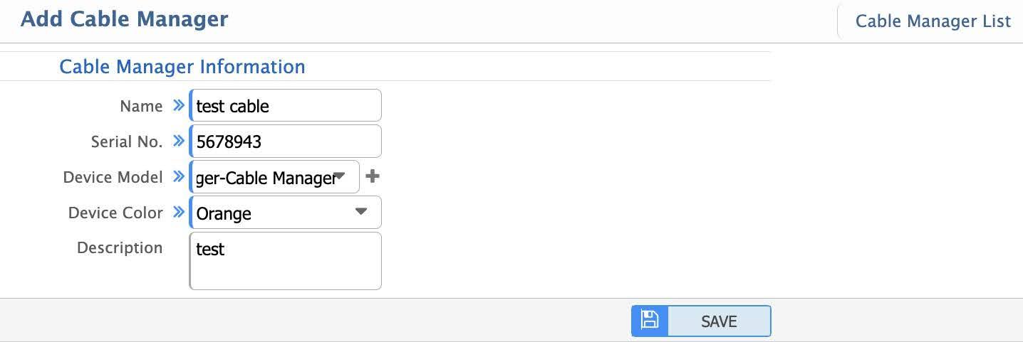
- Name: Unique name or identifier for the cable manager.
- Serial No: Unique serial number for inventory and tracking.
- Device Model: Manufacturer and model of the cable manager.
- Device Color: Color of the cable manager for easy identification and organization.
- Description: Additional details or notes about the cable manager.
Cable Manager List
Path: Install> Cable Manager > List Cable Manager
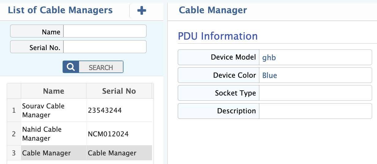
In this section, view a comprehensive list of all Cable Manager in the data center. It includes key details such as Device Model, color, socket type. Filter and search for specific Name, serial number.
UPS (Uninterruptible Power Supply)
An Uninterruptible Power Supply (UPS) is a critical component in a data center, ensuring continuous power during outages or fluctuations. It provides backup power to prevent downtime and protect sensitive equipment.
UPS Add
Path: Install> UPS > Add UPS
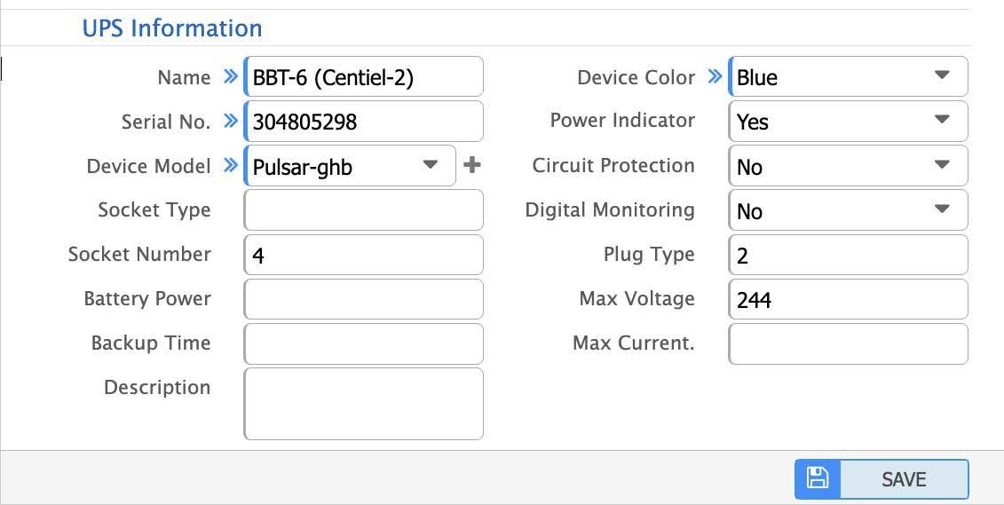
- Name: Unique name or identifier for the UPS.
- Serial No: Unique serial number for inventory and tracking.
- Device Model: Manufacturer and model of the UPS.
- Socket Type: Type of socket used by the UPS (e.g. IEC, NEMA).
- Socket Number: Number of sockets available on the UPS.
- Battery Power: Total battery power capacity (e.g. in kWh or Ah).
- Backup Time: Duration the UPS can provide backup power (e.g. in minutes or hours).
- Description: Additional details or notes about the UPS (e.g. purpose, location).
- Device Color: Color of the UPS for easy identification.
- Power Indicator: Indicates if the UPS has a power status indicator.(e.g. Yes, No).
- Circuit Protection: Indicates if the UPS provides circuit protection (e.g. Yes, No).
- Digital Monitoring: Indicates if the UPS supports digital monitoring (e.g. Yes, No).
- Plug Type: Type of plug used by the UPS (e.g. Type A, Type B, Type C).
- Max Voltage: Maximum voltage supported by the UPS (e.g. 120V, 240V).
- Max Current: Maximum current supported by the UPS (e.g. in Amperes).
UPS List
Path: Install> UPS > List of UPS
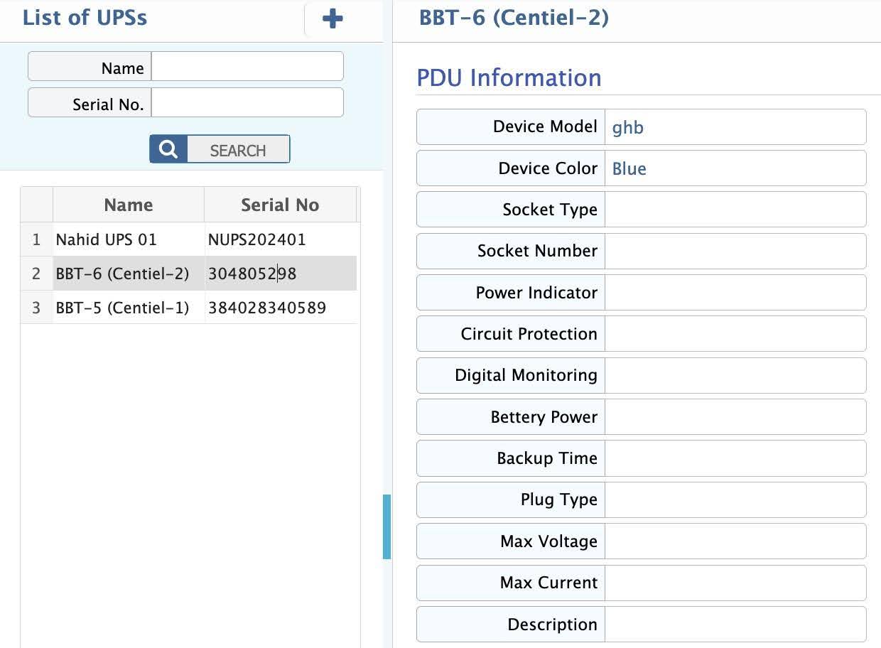
In this section, view a comprehensive list of all UPS in the data center. It includes key details such as device color, power indicator, circuit protection. Filter and search for name, serial number.
PDU (Power Distribution Unit)
A Power Distribution Unit (PDU) is a vital component in a data center, designed to distribute electrical power to servers, networking devices, and other IT equipment within a rack. It ensures efficient power management and load balancing.
PDU Add
Path: Install> PDU > Add PDU
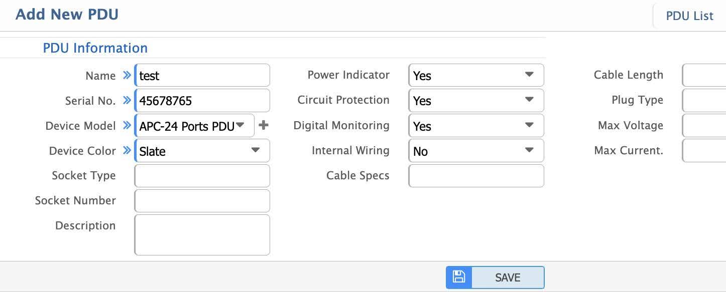
- Name: Unique name or identifier for the PDU.
- Serial No: Unique serial number for inventory and tracking.
- Device Model: Manufacturer and model of the PDU.
- Device Color: Color of the PDU for easy identification.
- Socket Type: Type of socket used by the PDU (e.g., IEC, NEMA).
- Socket Number: Number of sockets available on the PDU.
- Description: Additional details or notes about the PDU (e.g., purpose, location).
- Power Indicator: Indicates if the PDU has a power status indicator.
- Circuit Protection: Indicates if the PDU provides circuit protection (e.g.Yes, No).
- Digital Monitoring: Indicates if the PDU supports digital monitoring (e.g.Yes, No).
- Internal Wiring: Details about the internal wiring configuration of the PDU.
- Cable Specs: Specifications of the PDU's power cable.
- Cable Length: Length of the PDU's power cable.
- Plug Type: Type of plug used by the PDU.
- Max Voltage: Maximum voltage supported by the PDU (e.g., 120V, 240V).
- Max Current: Maximum current supported by the PDU.
PDU List
Path: Install> PDU > List PDU
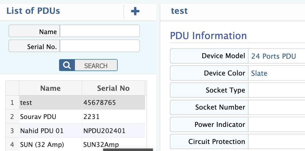
In this section, view a comprehensive list of all PDU in the rack. It includes key details such as device color, power indicator, circuit protection. Filter and search for name, serial number.
Configure Device
Rack Configuration
Rack configuration in a data center involves the structured arrangement of servers, networking devices, power units, and cabling within standardized racks to ensure optimal performance, cooling, and accessibility.
Do Configure (Rack Configure)
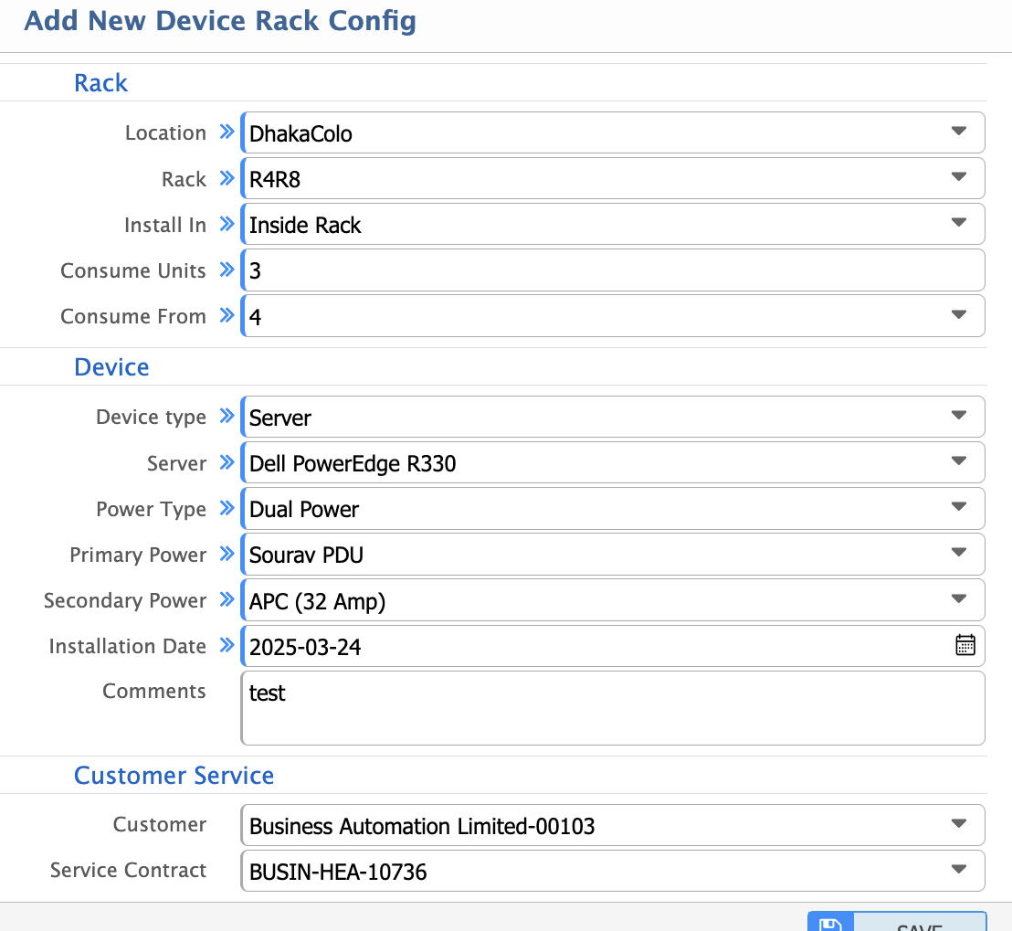
Path: Configure Device> Do Configure
- Location: Physical location of the rack within the data center (e.g. Room A, Row 1).
- Rack: Unique identifier or name of the rack.
- Install In: Specifies where the device is installed.
- Inside Rack: Device is installed inside the rack.
- Outside Rack: Device is installed outside the rack.
- Multi Device: Multiple devices are installed in the rack.
- Consume Units: Number of rack units (U) consumed by the device.
- Consume From: Starting unit from which the device consumes space (e.g. U10).
- Device Type: Type of device installed (e.g. server, ODF, switch).
- Power Type: Type of power configuration for the device.
- Single Power: Device uses a single power source.
- Dual Power: Device uses dual power sources for redundancy.
- Passive Device: Device does not require power (e.g. patch panel).
- Primary Power: Primary power source details (e.g. PDU A).
- Installation Date: Date when the device was installed.
- Comments: Additional notes or remarks about the device.
- Customer: Name or identifier of the customer associated with the rack.
- Service Contract: Details of the service contract (e.g. contract number, duration).
List of Configured Devices
A data center consists of various configured devices to ensure efficient operations, high availability, and seamless connectivity.
Rack List
Path: Configure Device> List of Configured Devices
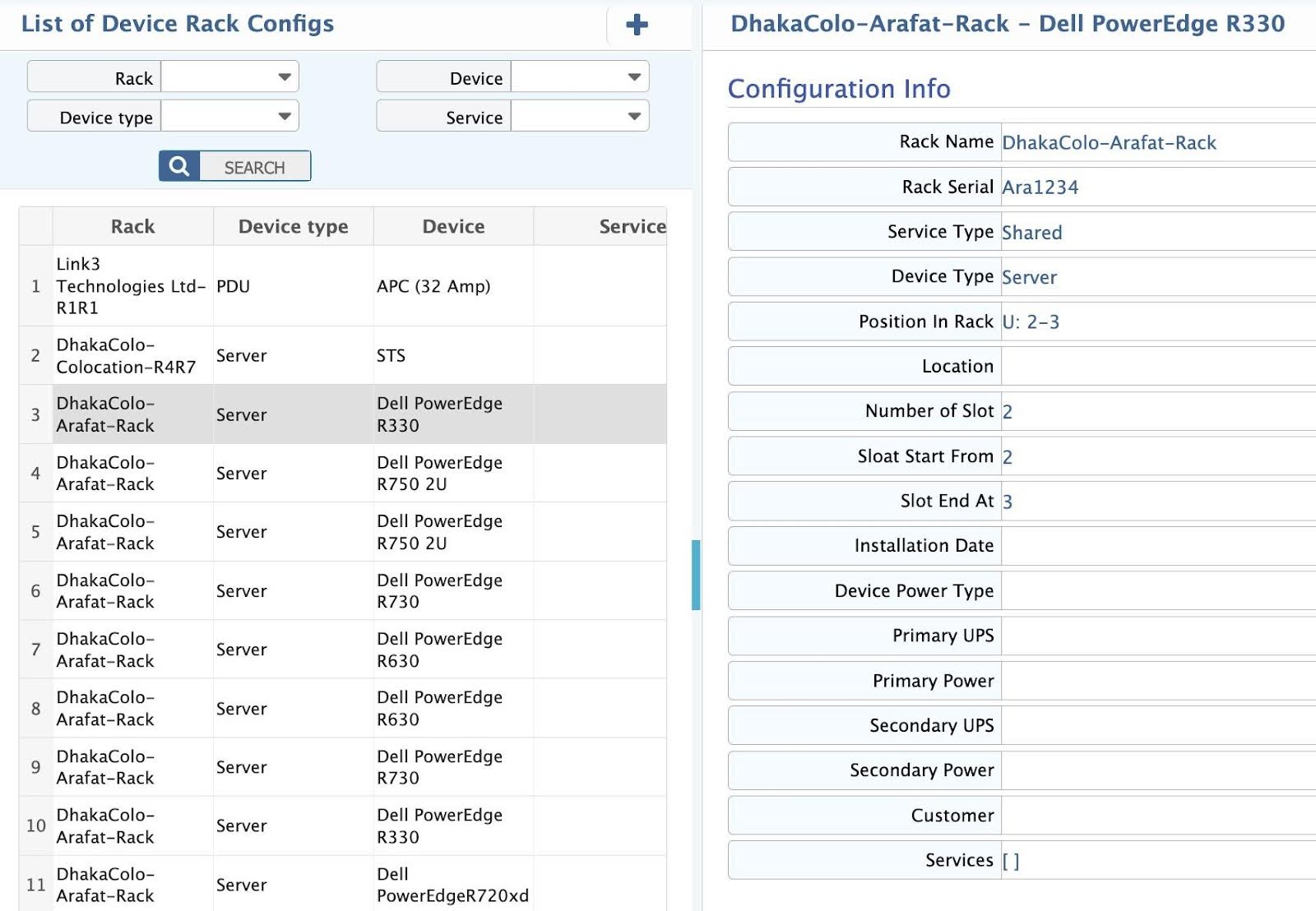
In this section, view a comprehensive list of all devices rack configs in the datacenter. It includes key details such as Rack, Device type, device, service name. Filter and search for name, serial number, service type, device type, position in rack, location, installation date, customer, service name etc.
Rack Layout
A rack layout diagram is a visual representation that outlines the arrangement of equipment, power, and cabling within a data center rack. It ensures optimal organization, efficient airflow, and accessibility for maintenance and upgrades.
Rack Layout Diagram
Path: Configure Device> Rack Layout
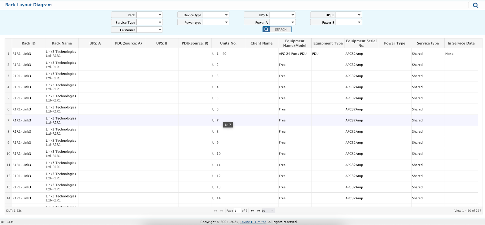
Rack Layout Diagram page in DCIM system provides a comprehensive view of a data center’s rack configurations, allowing operators to manage and monitor equipment placement, power distribution, and service configurations. The page includes various filters such as Rack, Service Type, Customer, Device Type, Power Type, and specific UPS and Power sources (A and B), enabling users to quickly locate and analyze data relevant to specific racks, customers, devices, and power setups. These filters help streamline operations, optimize resources, and ensure the proper functioning and redundancy of power systems for uninterrupted service delivery.